Instrumentation Amplifiers: Precision Measurement
An instrumentation amplifier, or in-amp, is a precision differential amplifier for small sensor signals riding on larger common-mode voltages. It is used with thermocouples, strain gauges, load cells, bridge sensors, current shunts, and biomedical electrodes.
Learning Objectives
By the end of this lesson, you should be able to explain how a three-op-amp instrumentation amplifier works, calculate gain resistor values, interpret CMRR, estimate sensor output scaling, and choose protection and filtering for real measurements.
Why Not Use a Simple Difference Amplifier?
A basic difference amplifier can subtract two voltages, but it loads the source unless resistor values are very high and accurately matched. In contrast, an instrumentation amplifier provides:
- very high input impedance on both inputs;
- high common-mode rejection ratio, often
80 dBto120 dB; - accurate differential gain set by one resistor;
- low offset, low drift, and low noise options;
- a reference pin for shifting the output into an ADC range.
Use an in-amp when the signal is small, differential, and vulnerable to common-mode noise.
Three-Op-Amp Architecture
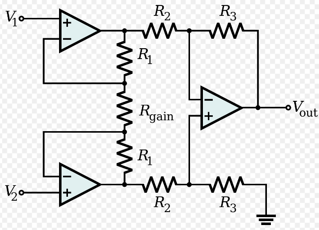
The classic in-amp has two stages:
- Input stage: two non-inverting amplifiers buffer the sensor and provide most of the gain.
- Difference stage: a matched-resistor subtractor removes common-mode voltage and produces one output.
The simplified gain equation is:
$$
V_{out} = \left(1 + \frac{2R}{R_g}\right)(V_2 - V_1)
$$
where R is the matched feedback resistor in each input amplifier and Rg is the gain-setting resistor between the two inverting nodes.
If Rg is open, gain is close to 1. As Rg becomes smaller, gain increases.
Worked Example: Gain of 100
Assume R = 10 kOhm and required gain G = 100.
$$
100 = 1 + \frac{2R}{R_g}
$$
$$
R_g = \frac{2 \times 10 k\Omega}{99} = 202 \Omega
$$
Use 200 Ohm or a precision 202 Ohm resistor. Use low-temperature-coefficient metal film parts when gain accuracy matters.
CMRR: Rejecting Common-Mode Noise
Common-mode voltage appears equally on both inputs. The in-amp should reject it while amplifying only the difference.
$$
CMRR_{dB} = 20 \log_{10}\left(\frac{A_d}{A_{cm}}\right)
$$
where Ad is differential gain and Acm is common-mode gain.
Examples:
60 dBmeans1000:1common-mode rejection.80 dBmeans10000:1common-mode rejection.100 dBmeans100000:1common-mode rejection.
If a sensor has a 5 uV wanted signal plus 100 mV of mains pickup, poor CMRR can leave more error than signal. High CMRR is one reason in-amps are preferred for bridge and biomedical measurements.
Thermocouple Scaling Example
A K-type thermocouple produces roughly 41 uV/degC near room temperature. For a 0 degC to 500 degC span:
$$
V_{sensor} = 500 \times 41 \mu V = 20.5 mV
$$
To map that span to 0 V to 5 V:
$$
G = \frac{5 V}{20.5 mV} = 244
$$
With the three-op-amp equation and R = 10 kOhm:
$$
R_g = \frac{20 k\Omega}{244 - 1} = 82.3 \Omega
$$
The circuit still needs cold-junction compensation, input filtering, and output offset management. Gain alone does not make a complete thermocouple instrument.
Bridge Sensor Example
A load cell often specifies sensitivity as 2 mV/V. With 5 V excitation:
$$
V_{FS} = 2 mV/V \times 5 V = 10 mV
$$
For a 0 V to 4 V ADC span:
$$
G = \frac{4 V}{10 mV} = 400
$$
The ADC resolution also matters. A 12-bit ADC over 0 V to 4 V has:
$$
LSB = \frac{4 V}{4096} = 0.977 mV
$$
Referred to the load-cell input after gain of 400, one ADC count equals about 2.44 uV at the bridge output. Noise, drift, mechanical hysteresis, and excitation stability may dominate long before ideal ADC resolution is reached.
Integrated In-Amps
Dedicated ICs such as AD620, INA128, INA333, and AD8421 include laser-trimmed resistors and published gain formulas. For example, the AD620-style gain relation is commonly written:
$$
G = 1 + \frac{49.4 k\Omega}{R_g}
$$
For G = 50:
$$
R_g = \frac{49.4 k\Omega}{49} = 1.008 k\Omega
$$
Always use the exact formula from the selected datasheet; internal resistor values differ by device family.
Reference Pin and ADC Range
Many in-amps have a REF pin. The output is measured relative to this pin:
$$
V_{out} = REF + G(V_2 - V_1)
$$
For a single-supply ADC, connect REF to mid-supply or to a precision offset when the differential signal can go positive and negative. Buffer the reference if the datasheet requires low impedance.
Protection and Filtering
Instrumentation inputs can be damaged by ESD, wiring mistakes, and large transients. A practical front end often includes:
- series resistors to limit fault current;
- matched RC filters on both inputs;
- differential capacitor across the inputs for high-frequency noise;
- low-leakage clamp diodes or dedicated protection devices;
- cable shielding and a defined sensor return strategy.
Keep input filters balanced. Unequal input impedance converts common-mode noise into differential error and reduces CMRR.
Practical Checks
- Verify input common-mode range at minimum and maximum sensor output.
- Check output swing at the chosen supply voltage.
- Confirm gain bandwidth at selected gain.
- Calculate input offset error multiplied by gain.
- Use a stable excitation source for bridge sensors.
- Route input traces symmetrically and away from switching nodes.
- Add an anti-alias filter before the ADC.
Common Mistakes
- Choosing gain before checking input common-mode range.
- Leaving the reference pin floating.
- Using unmatched input filters and losing CMRR.
- Expecting a high-gain in-amp to pass high-frequency signals without bandwidth loss.
- Ignoring thermocouple cold-junction compensation.
- Treating ADC resolution as true sensor accuracy.
Summary
Instrumentation amplifiers are the standard front end for small differential measurements. Their value comes from high input impedance, high CMRR, accurate gain, and a usable reference pin. A complete design still needs protection, filtering, common-mode checks, offset budgeting, ADC scaling, and careful layout.
Further Reading
- Analog Devices, "A Designer's Guide to Instrumentation Amplifiers."
- Texas Instruments, "Instrumentation Amplifier Application Guide."
- AD620, INA128, INA333, and AD8421 datasheets.
- Analog Devices MT-061, "Instrumentation Amplifier Basics."